- Tables
Tables
Exportar subconjuntos de datos de tablas
Exportar subconjuntos de datos de tablas a formatos dfb y excel
Exporting Tables to DBF and Excel
The application allows tables (whether layer attribute tables or separate alphanumeric tables ) to be exported in two formats:
- 1.Excel: Export data to a new Microsoft Excel file. The data appears on the second row of the first sheet. The first row contains the column names.
- 2.DBF: Export data to a dBase file.
Follow these steps to export a table:
A. Select the table:
To export a table it must first be opened. The export operations are activated once the table is opened.
To export a subset of the records use the selection tools to select the records to be exported. The records can be selected either from the attribute table or by selecting the corresponding geometries in the View.
B. Select the export option
To do this select the menu option:
For Excel: Table/Export/Excel.
For Dbase: Table/Export/DBF.
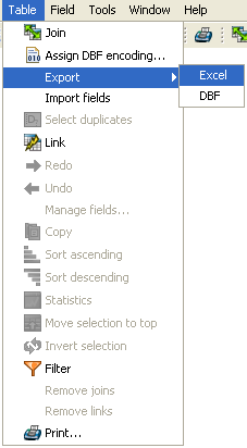
Export to Excel
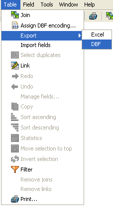
Export to DBF
C. Enter the file name
Locate the directory where you want to create the file and type a name for the file. If the file already exists the application will ask for confirmation to overwrite it.
Agregar información geográfica a la capa
Agregar información geométrica a la capa
In gvSIG, the Add geometric info tool is available when there are visible vector layers in the active View.
| Icon | Description |
|---|---|
 |
Add geometric info tool enabled if there are visible vector layers in the current view. |
 |
Add geometric info tool disabled if there are no visible vector layers in the current view. |
With this tool you can select which geometric properties to calculate for a visible vector layer in the current view, and then save these properties in the layer itself. The information can be saved in either new or existing fields in the layer's attribute table.
Once the above condition is met (i.e. a visible vector layer in the active View), the tool is available:
Via the menu: Layer → Add geometric info
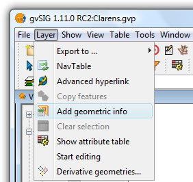
Selecting the Add geometric info tool from the menu
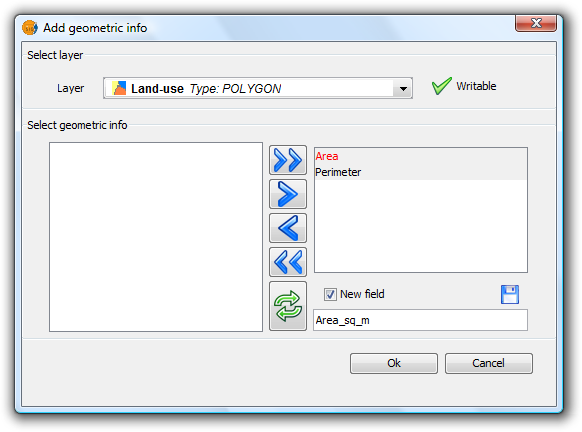
Selecting the tool displays a dialog where the attributes to be added can be selected:
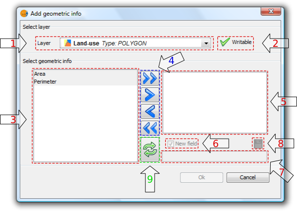
Add geometric information
1. Drop-down list for selecting vector layers. Lists the layers in the order that they appear in the TOC of the active view. The following information is shown:
- Postion of the layer in the TOC: displays various icons such as the layer grouping icon
 . The last icon always indicates a vector layer.
 - Name of the layer.
- Type of geometry of the layer: five types of layer geometries are supported: point, line, polygon, multipoint, and multi (which may contain any of the above).
2. Layer information writable. Indicates whether changes can be saved to the selected layer:
| Icon | Mode |
|---|---|
 |
Yes, changes can be saved. In this case the attributes to be added can be selected. |
 |
No, changes can't be saved. The tool will not list any attributes. |
3. List of geometric attributes. List of attributes of the geometry of the layer. These depend on the type of layer:
- Point layer:
- X coordinate
- Y coordinate
- Z coordinate
- Line layer:
- Length of the line
- Polygon layer:
- Perimeter of the polygon
- Area of the polygon
- Multipoint Layer:
- Number of points that make up the geometry
- Multi geometry layers: any of the above.
The geometric attribute will be associated with one type of geometry, which is identified by the icon on the left:
| Icon | Geometry type |
|---|---|
 |
The attribute is characteristic of point geometries. |
 |
The attribute is characteristic of multipoint geometries. |
 |
The attribute is characteristic of line geometries. |
 |
The attribute is characteristic of polygon geometries. |
4. Selection buttons. Allow attributes to be added to, or removed from, the list of geometry attributes to be calculated and saved for the vector layer.
| Icon | Option |
|---|---|
 |
Add all the geometric attributes to the list. |
 |
Add the selected geometric attributes to the list. |
 |
Remove the selected geometric attributes from the list. |
 |
Remove all the geometric attributes from the list. |
5. List of added geometric attributes. List of layer geometry attributes to be calculated and added.
Clicking on any of the attributes in this list enables the controls that allow the field to be renamed.
6. New field. This checkbox indicates whether the attribute is added as a new field, or as an update to an existing field in the vector layer.
 By default, every attribute is added as a new field.
7. Field name. New fields can have any name. Otherwise, select a field to update.
 The length of the field names is limited.
It is possible that the layer's alphanumeric encoding does not support some characters of the current language.
8. Save field settings. If the checkbox field is changed, or if another field name is specified, the changes can be saved by pressing this button.
Add geometric information
9. Reset. Resets the dialog by reloading the current View's visible vector layers, and by removing any selected attributes and their settings.
Once all the attributes have been selected, click the Ok button to start the process and display a progress bar.
Clicking the Cancel button, on the other hand, will terminate the tool.
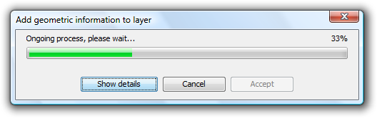
Progress of the Add geometric information process
- Progress bar: percentage of process completed.
- Show/Hide Details: show or hide the steps that have been completed.
- Cancel: Stops the process.
In the event of a serious problem, the process is terminated and an error message is displayed:
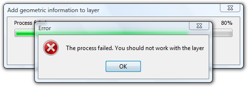
Error message
If the process completes successfully, the Accept button is enabled and the tool can be closed.
It is possible to view the steps that were performed by clicking the Show Details button in the dialog:
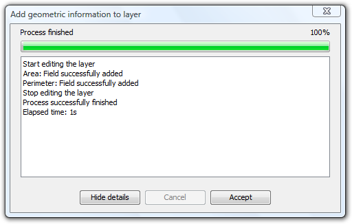
List of steps performed in adding geometric information
Do not use the gvSIG interface while the process is in progress as this can produce inconsistent data states, and even errors.
It should be noted that gvSIG currently adds the areas and perimeters of islands to that of the surrounding geometry.
EXAMPLE
Following the steps described in paragraph 5:
- A gvSIG project containing a view with a vector layer is loaded.
- The Add geometric information tool is loaded.
- The layer contains polygons so Area and Perimeter attributes are available.
- These two attributes are added as new fields with default names (Because of the shape encoding support the process removes accents and any occurrences of characters such as ç, Ç, ñ, Ñ).
- Click the OK button.
- Start and end the process successfully. Attributes are added as new fields in the selected vector layer.
- Click the Accept button to close the progress dialog.
- Open the layer's attribute table and move the horizontal scroll bar to the right to view the newly added attributes.
Example showing the calculated geometric information
Codificación de caracteres en tablas
Introducción
Although .dbf files should contain a byte to indicate character encoding, this information is usually not present. gvSIG provides the Shalom tool that sets the encoding and then reads the information in the table using that encoding. If the encoding is not set in this way then gvSIG will read the table data using the default encoding.
Asignar codificación a una tabla
It is possible to set the character encoding of a table by selecting Table > Set encoding to .dbf files from the menu bar. Choose the table for which the encoding needs to be set and then select the encoding type (charset). This encoding setting is recorded permanently in the table.
Now the table can be added to the gvSIG project. When gvSIG opens the table the character encoding is read and the characters in the table are correctly displayed.
Note: The correct display of characters depends not only on the encoding setting, but also on the virtual machine that is installed (specifically Java 1.6, which supports more encodings than Java 1.5).
Modificar codificación de caracteres por defecto
This option can be accessed by opening the Window > Preferences menu and then selecting DBF default encoding.
gvSIG will use the selected encoding as the default when adding a .dbf file to a project, and will also use it when exporting a table that uses a specific encoding.
The export of a table might not be correct if the character encoding is incorrectly configured in the gvSIG preferences.
Unión de tablas
The tool for joining tables has been improved and now reflects the relationship between the tables once they have been joined. The operation of the tool remains the same in that both tables must contain a common field that will be used to join them together.

Dialog for joining tables
It is possible to add a prefix to the source table fields so that they can be easily identified in the joined table, e.g. Table1_FIELD1, Table1_FIELD2, etc. In a similar manner a prefix can also be added to the target table fields: Table2_FIELD1, Table2_FIELD2, etc.
The resulting joined table is given a title made up of the tables participating in the join, e.g. Table1 X Table2 X, or vice versa.

Result of the table join
The join between the tables can be removed by selecting 'Remove joins' from the Table menu.
- Note: A layer can't be edited once a join has been established on it and the "Start Editing" option on the layer's context menu will be disabled. To start an editing session go to the Table menu and remove the existing joins.
Exportar estadíticas de tablas
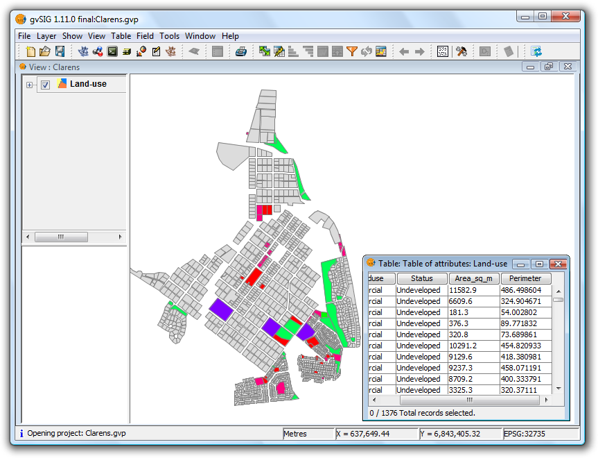
Esta herramienta añade la posibilidad de, una vez se muestran las estadísticas calculadas sobre un campo de la tabla, exportarlas en formato .dbf o .csv. Si sobre la tabla tenemos una selección de registros previamente hecha, las estadísticas se calcularán sólo teniendo en cuenta esos atributos seleccionados.
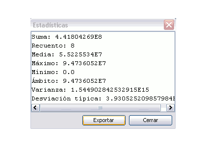
Cálculo de estadísticas sobre un campo.
Para exportar las estadísticas calculadas, presione el botón Exportar. Se abrirá una ventana donde seleccionar la ubicación de la tabla a crear, nombre y formato de salida (.csv o .dbf).
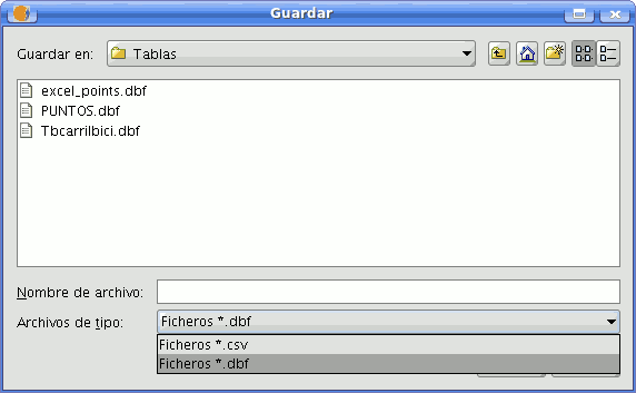
Selección de ruta, nombre y formato de tabla.
En caso de seleccionar como formato de exportación .csv se mostrará un nuevo panel donde el usuario elegirá el tipo de separador: Punto y coma, Coma, u Otro símbolo, este último determinado por el usuario.
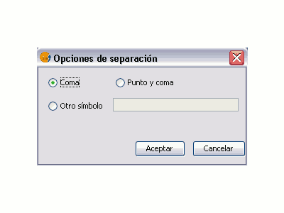
Selección de separador para tablas .csv
Un mensaje confirma que la exportación se ha realizado con éxito.
Tabla exportada correctamente.
