Edition
Snapping
En la primera página de edición puede configurar “Snap tolerance” . El “Snap” o “Snapping” es el proceso de mover un elemento hasta que coincida exactamente con las coordenadas de otro elemento. Si “Snap tolerance” es de 4 píxeles, dos elementos que se encuentren a una distancia igual o menor a 4 píxeles se unirán en una coordenada común.
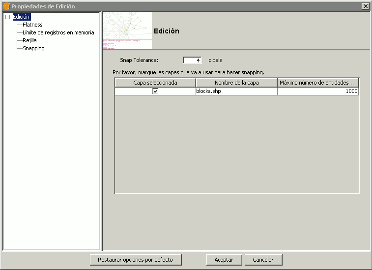
Ventana de propiedades de edicion.
Puede hacer snapping de elementos entre capas activando los check correspondientes en la columna llamada “Capa seleccionada”.
Puede modificar los valores de la columna “Máximo número de entidades en memoria” para acelerar los snappings y handlers en edición. Es el número máximo de geometrías con el que quiere trabajar en memoria.
Para hacer snapping a un determinado tipo de punto, activaremos la Rerferencia a objetos dentro del menú edición. Activaremos los tipos de punto a los que queramos hacer snap.
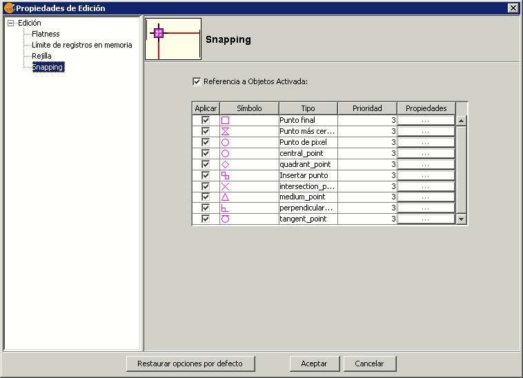
Opciones de Snapping. Referencia a objetos.
Matriz
The matrix command allows an item to be copied as many times as desired in a particular arrangement. The matrix can be of two types: rectangular matrix or polar matrix.
Right-click the layer you want to work with and select Start editing. Select an item, either a point, line or polygon, and then click on the Matrix tool. In the command window at the bottom of the screen the following instruction is displayed: Insert selection point. Clicking on the item opens the Matrix window.
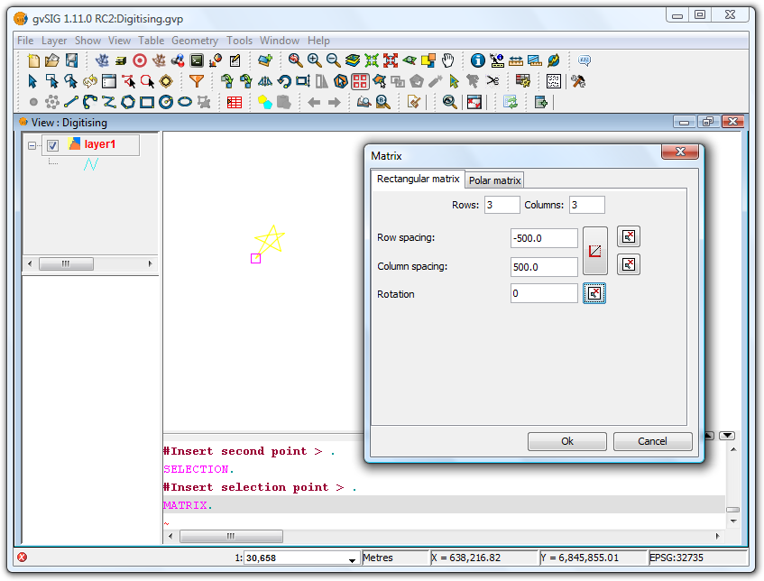
Matrix Window
Select the number of rows and columns by typing the values directly into the appropriate boxes.
The linear arrangement of the elements can be defined by typing the values manually, or by using the and
 icons to draw a direction vector or to define the extent of the matrix, respectively. In the second case, there are icons for defining the extent for each axis.
The matrix can be rotated by manually entering a rotation value or by clicking the icon and drawing the rotation angle in the View.
Using the values defined in the Matrix Window shown in the image above would produce the following matrix:
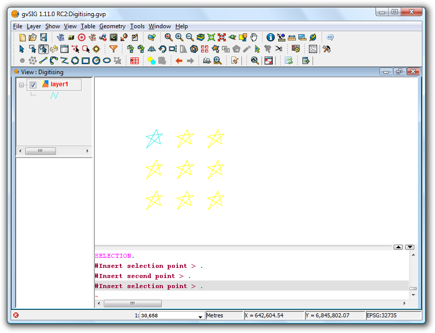
Final result showing the rectangular matrix
In the case of a polar matrix enter the source of the "system", the number of elements and whether the items should be rotated as they are copied.
Final result showing the polar matrix
Escalado
Mediante este comando podemos reducir o aumentar el tamaño de un objeto que se encuentre dentro de una capa sobre la que estemos trabajando. Para escalar un objeto, la capa en la que se encuentre debe encontrarse en edición.
Comenzamos la edición de la capa y pinchamos sobre el icono de escalado  que se encuentra en la parte superior de la ventana junto a otras herramientas de edición.
En la parte inferior de la ventana nos indica que precisemos el punto base sobre el cual el elemento aumentará o reducirá su tamaño. Una vez seleccionado disponemos de varias opcioens para realizar es escalado:
- Insertando el factor de escala (valor númerico).
- Mediante una referencia.
- Manualmente con el ratón, desplazandolo por la ventana hasta que consigamos visualizar el objeto con el tamaño deseado.
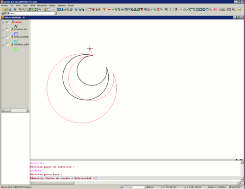
Escalado de un objeto lineal en gvSIG.
Explotar
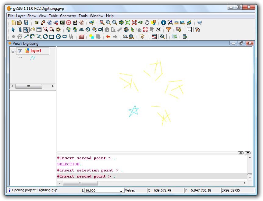
This tool is used to split a polyline into different segments.
To split a polyline, start editing the line layer and select the polyline:
Polyline selection
Once the polyline has been selected, activate the explode tool to split the polyine into segments. Verify that each of the segments can be selected as a line instead of as a poyline.

Explode button
Unir geometrias
The Join tool combines two or more geometries from the same polygon or line layer into a single multipolygon or multiline geometry. The tool can't be used with point layers as this would create a multipoint shape, which is already a shape-independent type.
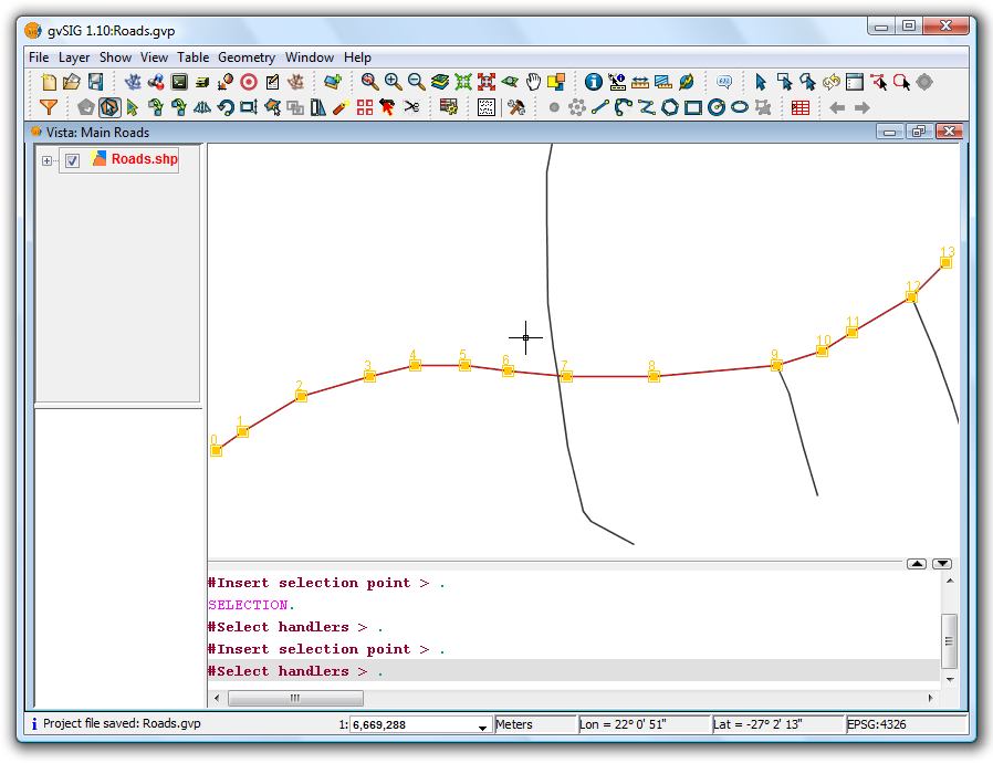
In order to use the tool the layer must be in edit mode. Use the Edit Selection tool to select the geometries to be joined, making use of the Ctrl key to select multiple geometries.
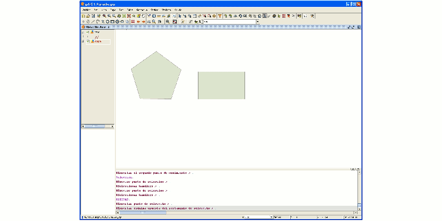
Selecting geometries to be joined
Once the geometries have been selected click the Join  tool to join the geometries into a single record in the table. It should be noted that the attributes of the geometry with the higher value 'Id' will be retained, i.e. the one that is drawn last.

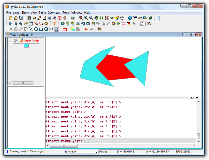
Example showing the result of the Join tool
Partir geometrias
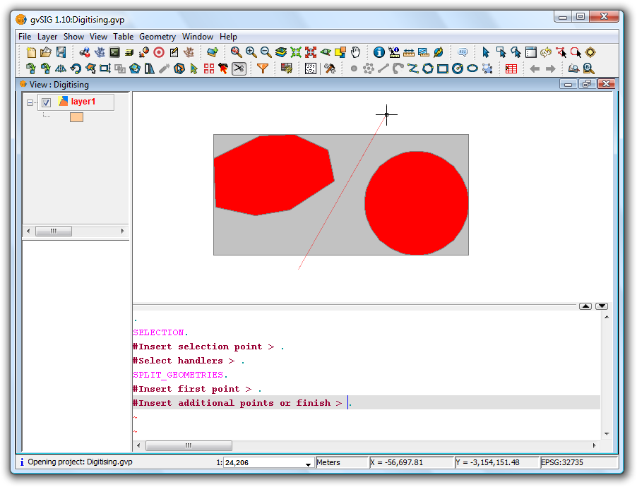
This tool splits geometries from the same layer. To perform the division, first switch the layer to edit mode and then use the selection tool to select the geometry to be split.
The "Split geometries"  tool can be found on the editing toolbar.
Once the geometry has been selected,

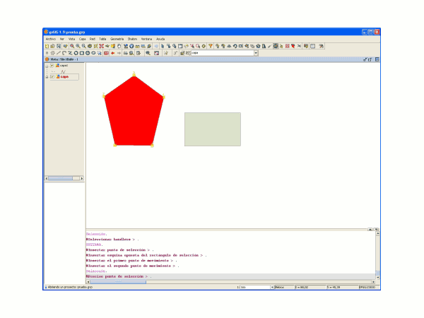
Selecting the geometry
click on the Split geometries icon. In the command window at the bottom the following message appears: "Insert first point." To split the geometry, draw a line where it should be divided. This is done by inserting a series of points that define the line along which the division is performed.
Splitting the geometry
Double-click to finish digitising the line and to perform the split. Then use the selection tool to verify that the geometry has been split into different parts.
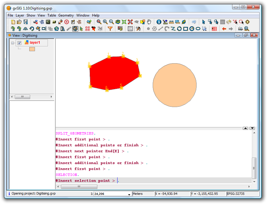
Result
The split operation results in the creation of separate records for each part in the attribute table, rather than the single record that existed prior to the split.
Autocompletar poligonos
This tool is useful for drawing polygons adjacent to existing ones, thus avoiding having to digitise all the vertices along the common boundary between the polygons.
Therefore it it only necessary to digitise the new sides of the polygon; the tool will automatically generate the common boundaries.
Apart from saving digitising or drawing time, this tool also eliminates overlaps and gaps between two polygons sharing a common boundary.
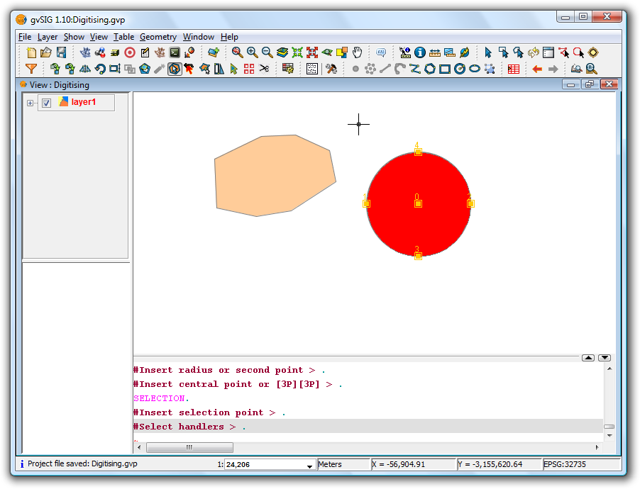
To use the tool first start editing the layer you wish to work with, and then activate the Autocomplete polygons icon  .
.
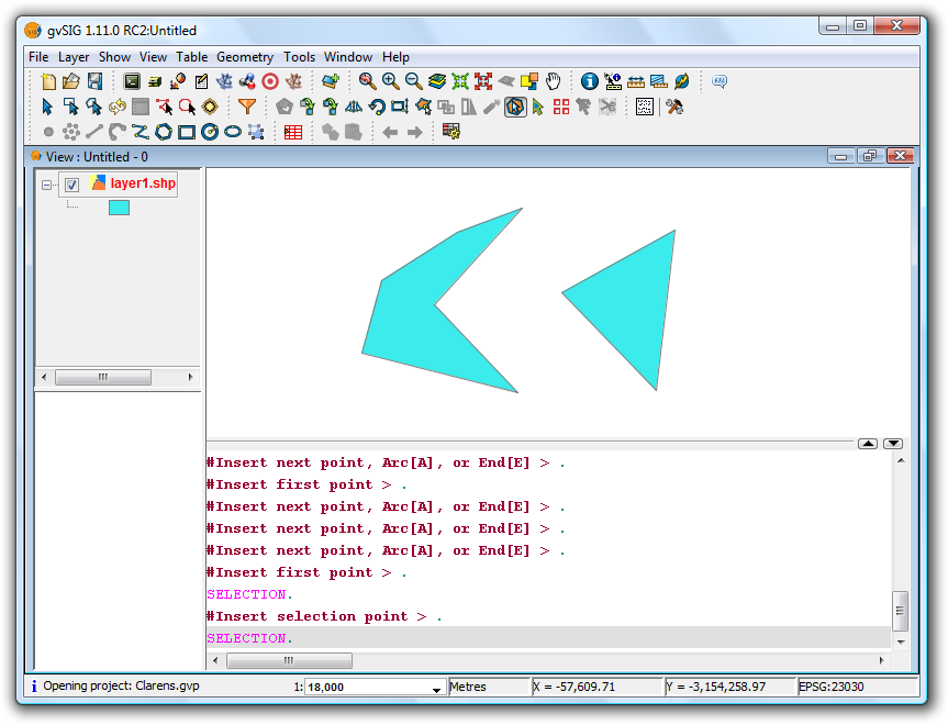
Example of use of the tool
The new polygon can now be drawn without having to digitise the nodes of common boundaries, as shown in the figure below.
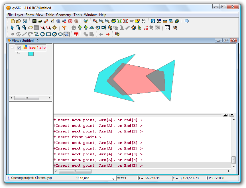
Example of use of the tool
Once all sides have been drawn, double-click the mouse or press "E" (end) to terminate the polygon. The figure below shows how the new polygon has been clipped to the common boundaries of the existing polygons.
Example of use of the tool
Estirar
Mediante la herramienta Estirar puede estirar una geometría, modificando su forma.

Icono de la herramienta Estirar
Para ello, ponga la capa en edición y seleccione la geometría a estirar. Pulse sobre la herramienta Estirar y, mediante el ratón, dibuje el rectángulo de selección de forma que queden incluidos los nodos de la geometría que desea modificar.
Selección de la parte de la geometría a estirar
Una vez seleccionados los nodos que desea desplazar inserte el punto de desplazamiento y posteriormente estire la geometría.
Resultado del polígono estirado
-----------------------------------
