Document Actions
Developers guide gvSIG
- Introduction
- It is all about extensions
- Andami and the management of windows
- Internal Libraries
- GVSIG
- Examples
- Introduction
- Hello World
- Personalized Information of a layer
- Editing
- Graphic Query
- Zoom to selection
- Farewell
Introduction
The present manual pretends to be of help for those who would like to develop over gvSIG. Because of that, and to be more useful the language would be simple and down to earth.
It is written for developers by developers. That means it is expected the lector is experienced in java programming.
To begin, gvSIG has been programmed with Eclipse. Other development platforms could be used, but all the examples in this manual were done with Eclipse (as well as the entire gvSIG).
Summing up: if you don’t know java or Eclipse it is recommended to begin learning them before you continue with this manual. (Forewarned is forearmed).
Another recommendation: in order to create extensions over an application, it is VERY recommended to know the application at depth. That is way it is very convenient to spend some time becoming familiar with gvSIG from the user’s side. There it is a manual on the web (http://www.gvsig.org) with more than 300 pages (Spanish for now), but that it is better used as a reference manual. There are shorter tutorials showing the most common options. However, when creating an extension consult the reference manual and become familiar with its usage.
The examples and diagrams are based on version 1.1.2 of gvSIG, official to date, although a new version would be available soon. Version 2.0 is being written, in many parts from scratch, so this manual will be discontinued upon the release of that version.
It is all about extensions
Introduction
The first thing we will look at is how gvSIG is organized internally.
One of the requirements for gvSIG was to be modular, that is, it should allowed for functionality improvements without having to modify the original code.
That is the reason we start from a nearly empty application that basically give us a windows manager and a load of plugins based on configuration files. The idea is exactly the same as the one used by Eclipse. Our plugings are the equivalent to the bundles from Eclipse, and Andami (our framework) is the equivalent of the RCP from Eclipse.
In a gvSIG installation, the andami.jar contains the base application, and the class that is executed is Launcher.java. Then we find the “extensions” directory, and inside that directory there are as many subdirectories as plugins installed in Andami.
Those subdirectories have the following structure:
A file config.xml where all the dependencies for that plugin are specified, the menus, toolbars and buttons that are available for the application and the implemented classes defined by the functionalities of the plugin.
A file .jar with the classes that make up the plugin (it can be with the file config.xml, or in some directory, e.g. lib).
Other libraries used by the plugin will be next to the .jar file mentioned before, usually in lib.
Other files used by the plugin (button icons and/or any other file to be used by that plugin.
The format for the config.xml file can be found in _fwAndami/schemas/plugin-config.xsd. Open the file with a text editor and read the comments. For example:
<!--
action-tool => Button which fires the execution of this extension

action-command Text to identify different action-tools inside a plugin
text Button's text.
name Button name (to retrive it)
icon Tool icon
last If true, a separator is added.
tooltip Tooltip
enable-text Text that describes the necessary conditions to enable a tool
position The position inside the toolbar
-->
<xs:element name="action-tool">
<xs:complexType>
<xs:attribute name="text" type="xs:string" use="optional" />
<xs:attribute name="name" type="xs:string" use="optional" />
<xs:attribute name="action-command" type="xs:string" use="optional" />
<xs:attribute name="icon" type="xs:string" use="required" />
<xs:attribute name="last" type="xs:boolean" use="optional" />
<xs:attribute name="tooltip" type="xs:string" use="optional" />
<xs:attribute name="enable-text" type="xs:string" use="optional" />
<xs:attribute name="position" type="xs:int" use="optional" />
</xs:complexType>
</xs:element>
Here it is defined how to specify a button “action-tool” type. An example of usage:
<extension class-name="com.iver.cit.gvsig.AddLayer"
description="Extension to open different layers."
active="true"
priority="20">
<menu text="View/Add_Layer" key="o" icon="images/addlayer.png"/>
<tool-bar name="View" position="2">
<action-tool icon="images/addlayer.png" tooltip="Add_Layer" position="1"/>
</tool-bar>
</extension>
We will see that the class containing the code to be executed when we click on the addlayer button it is called com.iver.cit.gvsig.AddLayer.java.
The toolbar containing that button is called “View”, and the button defines its icon (addlayer.png, inside the images directory), its position within the toolbar (it will be the first button) and the tooltip. The chain Add_Layer can be found in the .properties files. It is the code used for translating the text to the corresponding language. The remainder of the parameters are optional, thus they have not been defined.
The most important of all is that the config.xml file of an extension provides an excellent guide to understand what code we need to look at in order to know what a button or a menu option will do exactly when executes. The parameter class-name for the extension is the key, the class to look up and that will help us for copying its code whenever we want to create an extension similar to one that already exist.
Now we know how gvSIG is organised internally. The next step is to know how all the directories are generated, how the extensions are compiled, which extensions we can work with and what parameters gvSIG needs for star up. We will cover all those points next.
To compile a project
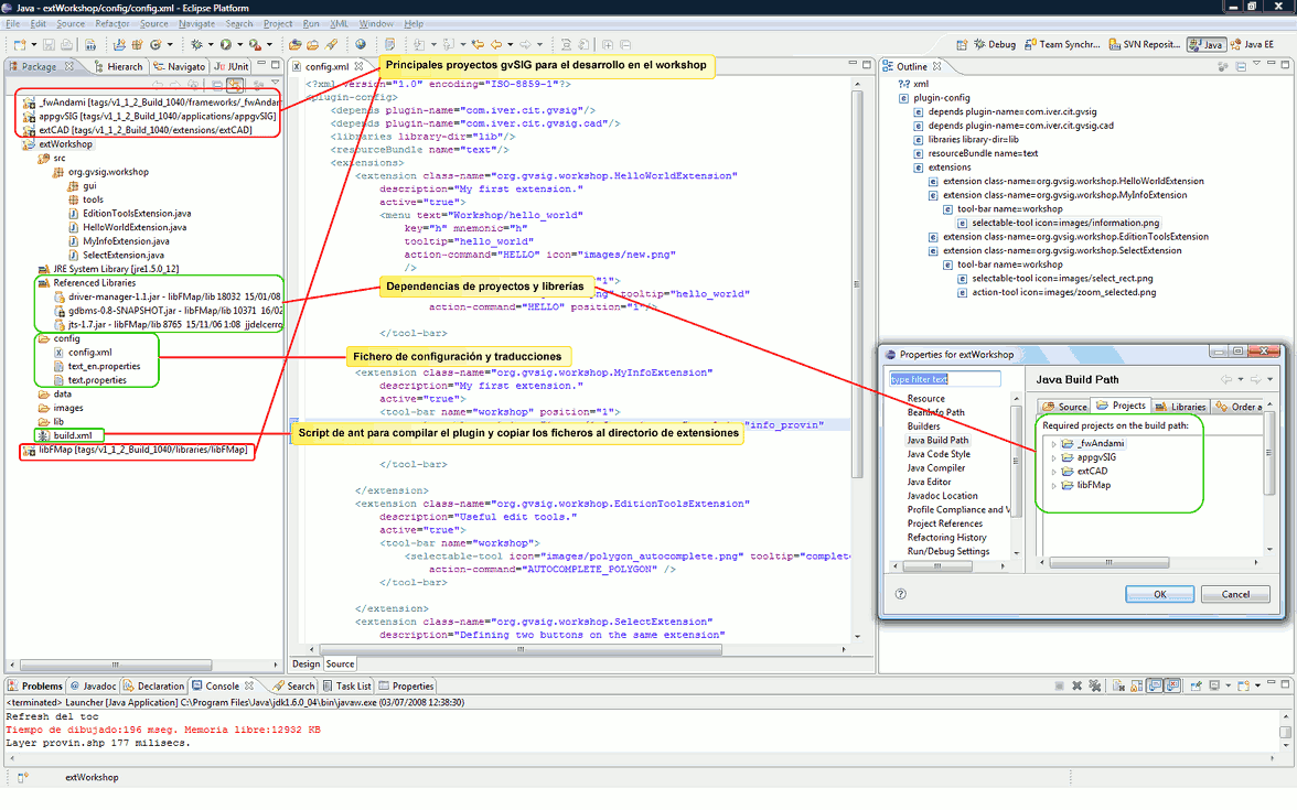
The following figure shows gvSIG version 1.1 open in Eclipse.
No reason to get over overwhelmed by the amount of projects (well, just a little bit...;-)). The first thing is to work with those that are indispensable. Later, if required we could modify or look at the code of the rest of the pluggings by opening and compiling those that we need.
VERY IMPORTANT: To execute the first compilation, follow the instructions from the Readme.txt file. In each distribution the method and/or the arguments could change some, but usually they are similar.
Basically there are 2 methods, one semiautomatic that compiles all the projects and another one "manual" that consists in finding the build.xml files of each project and execute them as ant targets. It is important to follow the established order in order to avoid problems.
Once the projects are compiled, we can start to work.
The best is to work only with those projects we are going to need. Close all the extension's projects you are not interested in, and leave open at least these ones:
- _fwAndami
- libCorePlugin
- libFMap
- appgvSIG
If you are interested in the editing functionalities, you should leave open the extCAD. If you would like to work with spatial database, leave open extJDBC. If your thing is raster, you will probably need libCq CMS for java and extRasterTools.
To start with, leave also an example project: extNewDocumentExample. It will help us as a starting point for our first pluggin.
Each project has a build.xml file that is executed as an ant target (mouse right click, run as... | ant tool.
In the build.xml file we define the name for our plugging, as well as the libraries and files that are needed to function. For example:
<project name="exaWorkshop" default="generate-without-source" basedir=".">
<description>
Examples for workshop on III Jornadas gvSIG
</description>
<!-- set global properties for this build -->
<property name="src" location="src"/>
<property name="build" location="bin"/>
<property name="dist" location="dist"/>
<property name="mainplugin" value="com.iver.cit.gvsig"/>
<property name="plugin" value="org.gvsig.workshop"/>
<property name="gvsiglibjar" value="org.gvsig.workshop"/>
<property name="andami" location="../_fwAndami" />
<property name="extensionsDir" location="../_fwAndami/gvSIG/extensiones"/>
<property name="lib-dir" location="${extensionsDir}/${mainplugin}/lib"/>

<target name="init">
<!-- Create the time stamp -->
<tstamp/>
<!-- Create the build directory structure used by compile -->
<mkdir dir="${build}"/>
<mkdir dir="${dist}"/>

</target>

<target name="generate-without-source"
description="generate the distribution without the source file">
<!-- Create the distribution directory -->
<mkdir dir="${dist}"/>

<!-- Put everything in ${build} into the MyProject-${DSTAMP}.jar file -->
<jar jarfile="${dist}/${plugin}.jar" basedir="${build}" includes="org/gvsig/workshop/**"
/>
<copy todir="${dist}/images">
<fileset dir="images" includes="*"/>
</copy>
<copy file="config/config.xml" todir="${dist}"/>
<copy todir="${dist}">
<fileset dir="config" includes="text*.properties"/>
</copy>
<move todir="${extensionsDir}/${plugin}/">
<fileset dir="${dist}" includes="**/**"/>
</move>
</target>


<target name="compile" description="compile the source" >
<!-- Compile the Java code from ${src} to ${build} -->
<mkdir dir="${build}" />
<echo>${compile-classpath}</echo>
<javac srcdir="${src}"
destdir="${build}"
debug="${debug}"
debuglevel="${debuglevel}"
classpath="${compile-classpath}"/>
</target>

<target name="copy-data-files">
<copy file="config/config.xml" todir="${dist}"/>
<copy todir="${dist}">
<fileset dir="config" includes="text*.properties"/>
</copy>
</target>

<target name="move-to-andami">
<move todir="${extensionsDir}/${plugin}/">
<fileset dir="${dist}" includes="**/**"/>
</move>
</target>


<target name="clean"
description="clean up" >
<!-- Delete the ${build} and ${dist} directory trees -->
<delete dir="${dist}"/>
<delete dir="${build}"/>
</target>
</project>
Inside the file will be defined the directories that are going to be used and where the results of the compilation will be saved. The most important variables are:
- ${extensionsDir} => The directory where we will copy everything.
- ${plugin} => The name of the plugging.
In the file you could see the targets defining it: to initialize, to erase the temp folder, to copy the files with the button icons, the config.xml file, etc.
The bold text is what you usually will need to change (the name of your pluggin and the classes your are including in the .jar, basically.
The easiest way to start a new gvSIG plugging is to copy this example, verify it compiles and works and then make the necessary changes to the package's name, the config.xml and the build.xml files. Then, the best thing is to look if there is any functionality already implemented within gvSIG that it is similar to the one we would like to implement. Probably that would be the case (click in the map, query a layer and display a form with the selected data, add a layer by code, add a table, open a project, zoom to selected, ...).
Once the common behaviors of our pluggins are identified, it is time to investigate which extensions within gvSIG can perform those tasks. We will see this with more calm later on, in the appgvSIG description, but for now it is enough to know that the starting point for our search is the config.xml, where we will find the menu or button and the class that gets executed upon selection of the option that we would like to use as a model.
Andami and the management of windows
The application or framework that serves as skeleton for gvSIG is _fwAndami (framework Andami). It has several functions:
- To send the application.
- To load plugins and its extensions.
- To manage the translations.
It offers services to the pluggins for the management and load of dependencies, handling of windows, for some utilities to send tasks into the background, etc.
The common libraries for the entire application is in the directory lib. Of special interest is log4j (registry of incidences), xerces (management of xml), castor (it is used to read xml of the project), gvsig-i18n (translations), beans (common graphic components), iver-utiles (generic useful classes).
Within Andami we find a series of classes that can be of utility for extensions. For example:
The class com.iver.andami. Launcher.java is the entry point to the application. In spite of being quite complex, when an extension sends an unexpected exception, it can sometimes easily be solved by adding a breakpoint to watch the class.
While working with our own extensions, we often needed to use the class com.iver.andami.PluginServices. As its name indicates, it is a class that yields service plugins, offering static methods like:
- getMainFrame () => the main application window
- getMDIManager () => through this class, we access the active window (PluginServices.getMDIManager () .getActiveWindow ()), something that we will continously use in the methods isEnabled and isVisible of all the extensions. It is also used to add a new window, and a few other minor things.
- getDlgPreferences () => obtain the common dialogue of preferences, where all plugin configurations are registered.
- getArguments () => recover arguments by command lines. For example, it is very useful for opening a project by line commands.
- getExtension (Class) => with this call, you can obtain an instance of the extension that executes that class. If the call is made in the initialize () method, you must be sure the extension has already been initialized (careful with the dependencies).
- getText (Object, String) => is used to work with translated text. From the plugin and a key, you obtain the string in the current language.
- registerKeyStroke (KeyStroke) => serves to determine the fast access global keys.
Additional methods exist, but the most frequently used are those we have described.
Andami is also responsible to manage a theme by default with the controls and the generic aspects of the application, to launch the welcoming image of the application (Splash Window) and other tasks we will not go into detail since you normally will not need to manipulate the code there.
The windows in Andami behave like generic units. That is, from the start, they do not depend on a Swing class. The reason is someday it may be decided to change this aspect of the application completely.
The plugin that instantiates the windows is the project libCorePlugin. In this plugin, the extensions are defined which connect the menu, control and window definitions with actual Swing objects. In our case, we chose to use the JInternalFrame class as the basis for gvSIG windows. Being this is an MDI (Multiple Document Interface) application, it seems most suitable.
The windows in Andami are defined thanks to the IWindow interface. This interface is very simple, it only requires to implement the getWindowInfo () method. This returns for a WindowInfo class where it is specified the size of the window, the title, and several constants indicating if the window is modal or not, resizable, or a pallette (very useful for showing information, a group of controls, or tools for example - it is always drawn over all other windows).
In order to show how to add a window in Andami, it is best to see an example:
PluginServices.getMDIManager().addWindow(symbolPanel);
where symbolPanel is
public class PanelEditSymbol extends JPanel implements IWindow {
We see that windows in gvSIG are in fact subclasses of JPanel implemented by the IWindow interface.
When we do not want to re-create a window again, but would rather reuse an already created window, we use the ISingletonWindow interface. This interface add a method (getWindowModel ()) that it is used for avoiding the creation of new windows if they have been previously created. That way it is avoided the creation of multiple windows with each requesting information click.
dlg = (DlgProvin) PluginServices.getMDIManager().addWindow(dlg);
for (int i=bs.nextSetBit(0); i >=0; i=bs.nextSetBit(i+1))
{
  long idRec = i;
  String nom = ds.getFieldValue(idRec, idField).toString();
  dlg.setProvinName(name));
}
where DlgProvin is defined as:
public class DlgProvin extends JPanel implements IWindow, SingletonWindow {
and the methods getWindowInfo
public WindowInfo getWindowInfo() {
  if (wi==null)
  {
      wi = new WindowInfo(WindowInfo.PALETTE);
      wi.setWidth(this.getPreferredSize().width);
      wi.setHeight(this.getPreferredSize().height);
      wi.setTitle("Provin Info");
  }
  return wi;
and getWindowModel:
public Object getWindowModel() {
  return "MyProvinDialog";
}
The windows currently in gvSIG are defined in libCorePlugin (the WindowInfo definition is used to create JinternalFrame windows). Sometimes it is useful to know in more detail how a window was created (to distinguish between SingletonWindow and other types, etc…). You can put a breakpoint in the class com.iver.core.mdiManager.NewSkin.java, in the function addWindow. rabajas which is a JinternalFrame. Be careful with this, future versions libCorePlugin might be changed to create a different type of window (this has not been planned, but is a possibility).
Internal Libraries
FMAP
We have tried to create libraries that are reusable outside of gvSIG. There are many libraries that can be used in such a way, and that can help with many of the problems a programmer can find in the Geographic Information Systems (GIS).
Among those libraries, there is one with the higher hierarchy for the programmer since it is the starting point for the majority of the libraries within gvSIG.
FMap can be seen as the graphic engine of gvSIG. It is the library that manages the layer collection gvSIG can work with and it is in charge of drawing those layers in a component (MapControl) in which the user can interact with.
Within the library there are some templates or typical tools defined (Behavior) with the usual user-map interaction behavior (look in the tools package).
For example, the behaviors of:
- Click in the map and execute an action based on the clicked point (show information) => PointBehavior.
- Move the mouse and execute an action based on the coordinates (show on the status bar) => MouseMovementBehavior.
- Draw a rectangle and execute an operation with it (select by rectangle) => RectangleBehavior.
- Click, move the mouse and realese (e.g. the pan tool) => DraggerBehavior.
- PolylineBehavior, PolygonBehavior, CircleBehavior => They allow the user to draw polylines, polygons or circles and they provide feedback to the user (the user sees how he draws these geometries).
These behaviors only launch events. In reality, the code executing what the user really wants is located in the listener classes. You can take a look to the classes PanListener, PointListener, CircleListener, etc.
The reason for this separation is that there are common behaviors to many of the tools. For instance, we can draw a rectangle and then added as a graphic in the map, or we can use the rectangle to execute a queryByRect over a layer.
As for the way to use it:
//Selection by polygon
PolygonSelectListener poligSel = new PolygonSelectListener(m_MapControl);
m_MapControl.addMapTool("polSelection", new Behavior[]{new PolygonBehavior(poligSel),   new         MouseMovementBehavior(sbl)});
The adequate listener is created and it is associated with a particular Behavior with the addMapTool method from MapControl. The “polSelection” chain is used internally to select a tool:
} else if (actionCommand.equals("SELPOL")) {
    mapCtrl.setTool("polSelection");
}
The most used classes in FMap (or at least in our opinion) are:
- MapControl. This is the component that shows the user the map, and over which it interacts with its tools. The most important method is getMapContext(), that returns objects of type MapContext.
- MapContext. This is the MapControl model. With it we have access to the collection of layers (vector, raster and of any type) and the object ViewPort, that defines the visible extent, the coordinate system being used, the projection, and some methods very useful to transform between the screen coordinates (pixels) and the real world coordinates (meter, km, etc.)
- FLayer. This is the common interface to all layers. It is the root to a hierarchical structure defining the types of layers that we will be working with. In FIGURE XXXX we could see this structure. The vector layers are FLyrVect and the raster layers are derived from FLyrRaster.
- The access to the vector data of a layer is done through the ReadableVectorial interface (FLyrVect.getSource()). With that we have the necessary methods to search through the features of a layer.
- IFeature => Geometry + alphanumeric data.
- SelectableDataSource (FLyrVect.getRecordset()). It offers access to alphanumeric data with the option to select records (getSelection()) and obtain information related to the fields of the associated table. It is also the internal model of any isolated alphanumeric table, not associated to any layer.
Layers are created (not mandatory) from the layer factory that joins the drivers (low-level access to the entities in the files or spatial database) with the vector layers and/or their legends by default. Example:
// Create a layer from a file-based driver
File fich = files[iFile];
String layerName = fich.getName();
String layerPath = fich.getAbsolutePath();
if (drivers[iFile] instanceof VectorialFileDriver) {
    lyr = LayerFactory.createLayer(layerName, (VectorialFileDriver) drivers[iFile], fich, proj);
}
A raster layer is created similarly from a RasterDriver:
if (drivers[iFile] instanceof RasterDriver) {
    lyr = LayerFactory.createLayer(layerName, (RasterDriver) drivers[iFile], fich, proj);
}
The low-level access to the data is based on a drivers system. The location of those reading drivers is specified with the call LayerFactory.setDriversPath(String path). This call needs to be done upon initialising the application.
We will also find in FMAP the drivers needed for working with layers of different formats, especially those that are vector, since originally FMAP was created as a library to manage vector data.
In gvSIG, the drivers should be in the gvSIG/extensiones/com.iver.cit.gvsig/drivers directory. There it should be found the drivers to access shp, dxf, dgn, dwg, mysql, postgresql, oracle, gml, etc.
The drivers are managed by the libDriverManager library. The condition a driver must comply is defined by the Driver interface, that it only requires a name for that driver (to find it in the registered driver collection (getName()). Curiously enough, there is an additional strange condition: the classes that are drivers must be named WhatEver**Driver**.java. That is, they should end in the world Driver.
That is all as for the data reading. Data writing follows a similar structure. There is an interface IWriter that inherits from Driver and that defines de writing methods. We will come back to data edition later, since it is a very complex subject.
The union of the layer with the driver is done according to the pattern Adapter. There are internal classes that can adapt the driver’s methods to the requirements of a layer reading.
The package com.iver.cit.fmap.drivers contains the classes and the interfaces for the data reading. To be revised: ITableDefinition, ILayerDefinition, VectorialDriver and their derived interfaces: IFeatureIterator, MemoryDriver y ConnectionFactory.
A typical question that shows up once in a while:
Where can I see the code that draws gvSIG?
There is no a simple answer. In addition, the symbology part of the next gvSIG versions is going through a spectacular change, thus anything it is said here may not be valid for the next version. However, let’s concentrate on the areas that will not change.
We have said that MapControl is the component that shows the map and the one the user interacts with. However, MapControl is not responsible for drawing the map, it manages the drawing requests and it keeps a Timer that allows to refresh the component every once in a while so the user sees the map drawing. The real drawing DOES NOT happen over the MapControl Graphics. In fact, it is MapContext the one drawing in the background over a graphic that MapControl has obtained from a BufferImage.
So the quick answer is that what we see it is happening in a separate thread, so the user will not notice the interface slowing down and that it is drawn over an image in memory.
If we look at the MapContext code, we will find the following method:
public void draw(BufferedImage image, Graphics2D g, Cancellable cancel,
                double scale) throws DriverException {
        if (viewPort.getExtent() == null) {
                // System.err.println("viewPort.getExtent() = null");
                return;
        }
        System.out.println("Viewport after: " + viewPort.toString());
        /*
         * if ((viewPort.getImageWidth() <=0) || (viewPort.getImageHeight() <=
         * 0)) { return; }
         */

        prepareDrawing(image, g, scale);

        // More text quality
        RenderingHints renderHints = new RenderingHints(
                        RenderingHints.KEY_ANTIALIASING,
                        RenderingHints.VALUE_ANTIALIAS_ON);
        renderHints.put(RenderingHints.KEY_RENDERING,
                        RenderingHints.VALUE_RENDER_QUALITY);
        renderHints.put(RenderingHints.KEY_TEXT_ANTIALIASING,
                        RenderingHints.VALUE_TEXT_ANTIALIAS_ON);
        g.setRenderingHints(renderHints);

        long t1 = System.currentTimeMillis();
        layers.draw(image, g, viewPort, cancel, scale);

        LayerDrawEvent beforeTracLayerEvent = new LayerDrawEvent(tracLayer,
                        g, viewPort, LayerDrawEvent.GRAPHICLAYER_BEFORE_DRAW);
        fireLayerDrawingEvent(beforeTracLayerEvent);
        tracLayer.draw(image, g, viewPort, cancel, scale);
        LayerDrawEvent afterTracLayerEvent = new LayerDrawEvent(tracLayer,
                        g, viewPort, LayerDrawEvent.GRAPHICLAYER_AFTER_DRAW);
        fireLayerDrawingEvent(afterTracLayerEvent);

        //layers.setDirty(false);

        long t2 = System.currentTimeMillis();
        System.err.println("Drawing Time:" + (t2 - t1) +
                        " mseg. Free Memory:" + Runtime.getRuntime().freeMemory() / 1024  + " KB");
        /*
         * Free resources
         */
        System.gc();
}
At least there are 3 important things to stand out.
The first one is the object Cancellable. It is used for interrupting the drawing, and within the layer extent, it verifies if the object returns true (it has been cancelled) while it is drawing the geometries. If that is the case, it has to get out of the geometries extent. This is important if anytime we would like to implement a different drawing strategy to the ones already implemented and we would like to keep the option of interrupting the drawing. If we do not want the interruption, we could pass a Cancellable object to this method that will always return false. The second one refers to the line
layers.draw(image, g, viewPort, cancel, scale);
layers is the collection of layers of our object MapContext. It is an object of type Flayers, which means that we have follow here the pattern Composite to implement the layer grouping. A collection of layers behaves in turn as a layer itself. Internally it will search through the layers forming the grouping and it will call the draw method of each of one of them. The third one to show up is the layer TrackLayer. It is a layer used for drawing graphics on top of all the other layers (persistent graphic). It is important to also notice the events that are thrown BEFORE and AFTER of drawing the layer. If we ever need to do something after drawing the map (e.g., zoom in an area and show the user a dialog box related to the area), the best option is to create a listener of that event, and to put the code in response to
LayerDrawEvent.GRAPHICLAYER_AFTER_DRAW.
If we do not do it this way, the user will not see the area that he want it to see, since the drawing of the mapcontext happens in another thread and over an image on memory. Those events allow us to be certain that the image on memory has already being drawn.
Also, there are events launched before and after the drawing of each layer. You can check the events LayerDrawEvent and the interface LayerDrawingListener.
Another interesting package to check is com.iver.cit.gvsig.fmap.core. The hierarchic structure of the geometries in FMAP is defined inside. You can check a summary in FIGURE XXX.
The geometries are one of the things (together with everything relative to legend and symbology) that can change the most in versions 2.0 and up.
The reasons is that while this manual is been created, gvSIG is being developed with drawing capabilities available until now in very advance commercial products.
Another of the great internal advances that is being prepared is the possibility to create topology over the layers, edit nodes, create polygons automatically from lines and to associate restrictions and validations to all the system.
Symbology is the part that most will affect the legend, and very likely the geometries will change to allow for the new options of validation and topology.
For now, the least likely to change is that there it would be an interface that is the father of all the geometries (IGeometry). Internally, for the present one works with FGeometry, that normally it is based on the GeneralPathX geometry. This class is exactly the same as GeneralPath, except that the coordinates are kept in a double array instead of a float array.
Examples of FMAP Usage
Add a layer by code
To add a layer by code usually it is necessary to create the driver and then to call LayerFactory. Let’s take a look:
LayerFactory.setDriversPath(
    "C:\\eclipse3\\workspace\\Andami\\gvSIG\\extensiones\\com.iver.cit.gvsig\\drivers");
FLayer l = LayerFactory.createLayer("Vias",
    (VectorialFileDriver)   LayerFactory.getDM().getDriver("gvSIG shp driver"),
    new File("C:/vias.shp"),
    CRSFactory.getCRS("EPSG:23030"));
newMapControl.getMapContext().getLayers().addLayer(l);
A PostGIS layer is created as follows:
String dburl = "jdbc:postgresql://localhost/latin1";
String dbuser = "postgres";
String dbpass = "XXXXXXX";
    // String dburl = "jdbc:postgresql://192.168.0.217/postgis";
// String dbuser = "gvsig";
// String dbpass = "";

    // String dbtable = "carreteras_lin_5k_t10";
String dbtable = "provin"; // BECAREFUL WITH CAPITAL LETTERS!!!!!!!
IConnection conn = null;
System.out.println("Creating JDBC connection...");
Class.forName("org.postgresql.Driver");
conn = ConnectionFactory.createConnection(dburl, dbuser, dbpass);

((ConnectionJDBC)conn).getConnection().setAutoCommit(false);

DBLayerDefinition lyrDef = new DBLayerDefinition();
lyrDef.setName(dbtable);
lyrDef.setTableName(dbtable);
lyrDef.setWhereClause("");
String[] fields = {"nom_provin", "gid"};
lyrDef.setFieldNames(fields);
lyrDef.setFieldGeometry("the_geom");
lyrDef.setFieldID("gid");

Statement st = ((ConnectionJDBC)conn).getConnection().createStatement(ResultSet.TYPE_SCROLL_INSENSITIVE, ResultSet.CONCUR_READ_ONLY);
    rsGood = st.executeQuery("SELECT NOM_PROVIN, GID FROM " + dbtable           + " ORDER BY GID");
    driver.setData(conn, lyrDef);
}
catch (Exception e){
    e.printStackTrace();
}
It is necessary to notice a vector layer is defined normally based on a driver and an object ILayerDefinition, where there are specified the layer’s name, fields, coordinate system, etc.
Spatial Query
Spatial queries are very common. For example, we search for features within a determined polygon (the same as searching for something using certain tolerance).
There are several ways to do it and they can be consulted by looking at the codes for the information and selection tools in gvSIG. Here we will show a simple one, especially to demonstrate the FBitMap usage.
The FBitMap class represents a selection of records. It is based on the Bitmap Java class, which contains 0 and 1, a “1” when the record is selected and a “0” when it is not selected. The advantage of this binary storage is the very low memory space taken by the selection and easiness to iterate, count, change the selection, etc.
The disadvantage is that we start from the assumption we always have a random access available to our driver. In other words, the operation to get the umpteenth record is available and fast. That allows us, if there are 10 records selected to obtain their record numbers, get their Feature and do something with them. The problem arises when the data sources do not allow for this type of random access and return their Features in a sequential manner, without knowing how many records will be returned before hand.
That is why we cover BitMap with FBitMap, so in the future we can deliver a selection adapted to databases with random or sequential access.
Then, upon a selection the driver is run from beginning to end while the condition is evaluated (spatial and/or alphanumeric) and the selected records are marked with bitmaps. If any driver were only sequential, we would have to storage the selected records in an array or something similar to avoid searching through the database to position the records, which would be a slow operation.
Nowadays, the drivers in gvSIG are sufficiently fast to allow for random access. Therefore, we can make a query such as:
Point2D p = event.getPoint();
Point2D mapPoint = mapCtrl.getViewPort().toMapPoint((int) p.getX(), (int) p.getY());

// 3 pixels tolerance
double tol = mapCtrl.getViewPort().toMapDistance(3);
FLayer[] actives = mapCtrl.getMapContext()
.getLayers().getActives();
for (int i=0; i < actives.length; i++)
{
    if (actives[i] instanceof FLyrVect) {
        FLyrVect lyrVect = (FLyrVect) actives[i];
        FBitSet oldBitSet = lyrVect.getSource().getRecordset().getSelection();
        FBitSet newBitSet = lyrVect.queryByPoint(mapPoint, tol);
        if (event.getEvent().isControlDown())
            newBitSet.xor(oldBitSet);
        lyrVect.getRecordset().setSelection(newBitSet);
    }
}
This code has been extracted from the com.iver.cit.gvsig.fmap.tools.PointSelectionListener.java class. What is does is to receive a point in pixels, transform it to map coordinates and search through all the active layers. If they are of vector type, it uses the queryByPoint query to obtain the FBitSet (the selection).
Then we can use this selection for anything we want. The search through the selected records is done this way:
SelectableDataSource ds =lyrVect.getRecordset();
int idField = ds.getFieldIndexByName("NOM_PROVIN");
FBitSet bs = lyrVect.queryByPoint(mapPoint, tol);
for (int i=bs.nextSetBit(0); i >=0; i=bs.nextSetBit(i+1))
{
    long idRec = i;
    String nom = ds.getFieldValue(idRec, idField).toString();
    dlg.setProvinName(nom);
}
Here we have selected the province that contains the point “mapPoint” and we have search through the selected records, recovering the field value “NOM_PROVIN”.
We will see more examples in chapter 6.
GVSIG
Introduction
In this chapter we will see how the gvSIG application is organized internally. We will start with the main body (appgvSIG) and we will see how its functionality has been extended based on extensions.
In fact, appgvSIG is in itself another of Andami's plugging, containing the extensions that defines the basic functionalities of gvSIG.
gvSIG is internally organized similarly as it is organized externally. That is, there are classes controlling the gvSIG project and the project is composed at the same time by various types of documents (Views, Maps, and Tables) although they can be extended by other types of documents.
The packages are organized according to this structure:
NOTE: The structure could seem somehow arbitrary (in fact, it is :-(). But it is the one available, and we will try to describe a little the packages. In the future they shall be re-organized.
- The classes implementing IExtension are in the root package: com.iver.cit.gvsig. This is something that has been followed by the developers and it seems to be a sound practice. This way it is easier to find which are the entry points for the options in the menus, buttons, etc.
- The package com.iver.cig.gvsig.project is a good entry point to get acquainted with gvSIG. In theory, gvSIG follows a structure which is influenced by the organization by documents within a project. The most important classes here are Project.java and ProjectFactory.java. The first one represents the gvSIG project and the static method createFromXML() is the entry point to see how to read a .gvp file (gvSIG project). The contrary step, create a .gvp file is done with the writeProject method of the ProjectExtension extension and it calls the getXMLEntity() method from the Project class.
- Within the project package is the com.iver.cit.gvsig.project.documents package. We will find there the ProjectDocument and ProjectDocumentFactory classes. The first one is the class from which the rest of the documents inherit (can be selected and use the F4 key). The second is the one responsible for creating the documents and manage the potential documents that in the future could expand the model of objects, for example with 3D views.
In the rest of the packages we will find the classes related with the layout, view and table. Within contextMenu the context menus and in the other packages some exceptions and the user interface classes to add layers (GUI)
The rest of the packages do not follow a set logic or at least it is not apparent. Surely they will be reorganized in the future. However, in case you ever need to look for code, it is possible you could be interested to look at com.iver.cit.gvsig.gui.layout. Within this you will find the Layout class, responsible for the maps prepared for printing and the classes within the fframes package, were you could see all that can be added to a layout (views, legends, north arrows, text, graphics, scale, etc). This area is waiting for a rebuild that will allow for easy expansions from external plugging’s.
An interesting class to begin to explore when you are working at this project level is the com.iver.cit.gvsig.ProjectExtension class. This is the entry point to the operations of creating a new project, loading an existing one, save it, etc.
Once introduced (although briefly and superficially) the packages structure, let us take a closer look at the principal parts of gvSIG. Or at least those you would work most likely.
Views
Introduction
The default view in gvSIG (the one everyone is used to see) basically contains a MapControl object (where the layers are drawn), a MapOverview object (the locator which inherits from MapControl) and a table of contents (ToC) where the user can see the available layers, their drawing order, etc.
In the 3D pilot there it has been created a new type of view (3D) and in doing so it has been implemented a mechanism so different types of vista can be defined.
View
Introduction
A view relates to the project through the class com.iver.cit.gvsig.project.documents.ProjectView. The object com.iver.cit.gvsig.project.documents.view.gui.View is created with the method createWindow() and the model is assigned to it. The model is the ProjectView document that has a MapContext associated to the MapControl and another MapContext that corresponds with the layers of MapOverview. The ToC is in reality another way to view the MapContext associated to the MapControl.
View has also a console that is used when a layer in being edited, so the user can key in the editing commands as in a CAD software.
MapControl
In many extensions the first thing is to obtain the object View and from that to obtain the associated MapControl and MapContext. This is usually the entry point. With the MapContext we have already the list of layers (Flayers), search tool for the layer that we would like to work with, etc. Let’s take a look at an example:
com.iver.andami.ui.mdiManager.IWindow view = PluginServices.getMDIManager().getActiveWindow();
if (!(view instanceof View))
    return;
View vista=(View)view;
IProjectView model = vista.getModel();
MapContext mapa = model.getMapContext();
MapControl mapCtrl = vista.getMapControl();
logger.debug("Comand : " + s);

if (s.equals("FULL") ) {
    try {
        // mapa.beginAtomicEvent();
        mapa.getViewPort().setExtent(mapa.getLayers().getFullExtent());
        mapa.clearAllCachingImageDrawnLayers();
        vista.repaintMap();
        // mapa.endAtomicEvent();
    } catch (DriverException e) {
        NotificationManager.addError("Error getting full extent",
            e);
    }
}
This portion of code comes from the com.iver.cit.gvsig.ViewControls class. It uses PluginServices.getActiveWindow() to obtain the active window. If that window is of type View, then it gets the MapContext to show a zoom of all the layers:
mapa.getViewPort().setExtent(mapa.getLayers().getFullExtent());
The most interesting classes to review to see examples of this type are:
- ViewControls.- They are many commands in only one class: full extent, panning, configure locator map, zoom in, zoom out, meassure, set layers as visible, not visible, active, not active, save to raster, change scale...
- ViewSelectionControls.- Select by point, by rectangle, by polygon, by layer and invert selection.
- Export.- Exports to raster what is visible in a view.
- AddLayer.- It is used for adding layers to a view. It is far more complex of what it looks like, since it shows a dialog box extensible from external pluggings. In fact, it is used by other pluggings to add layers based on spatial databases, WMS, WFS, etc. In this class there is only the necessary to add layers based on files (.shp, raster, .dxf, .dgn, etc). It is also important that you pay attention to the projection treatment associated to the layer and the view. If they do not coincide, it will try to reproject on the fly.
- InfoToolExtension.- The window to show information is far more complex of what it looks like (perhaps far more than necessary). This class is only the entry point to find out its functioning.
Within the views it is very interesting to see the relationship between the MapOverview and the MapControl. We will see it next.
MapOverview
A MapOverview is a subclass of the MapControl, with the particularity that is linked to the MapControl within the View document. By default it is on the lower left corner, and it allows for any kind of layer to be loaded onto it and for the management of its legend. It is usually used as a locator, showing some location layers and a rectangle that shows the visible rectangle of the associated MapControl.
The MapOverview is a listener of the MapControl, so that any change in the visualisation of an area makes the MapOverview to update and show the corresponding area shown by the MapControl.
The code responsible of this behaviour is:
public void setModel(MapContext model) {
    this.setMapContext(model);
    model.setProjection(m_MapAssoc.getMapContext().getProjection());
    m_MapAssoc.getMapContext().getViewPort().addViewPortListener(this);
    getMapContext().getViewPort().addViewPortListener(this);
}
On having associated the MapOverview model, this is added as a listener to the viewPort of the main MapControl.
public void extentChanged(ExtentEvent evExtent) {
    // We get the new extent of the associated FMap, so we draw our
    // rectangle to show the drawing area of the other map.
    repaint();
}

protected void paintComponent(Graphics g) {
    super.paintComponent(g);
        if ((m_MapAssoc.getMapContext().getViewPort().getExtent() != null) &&
                (getMapContext().getViewPort().getExtent() != null)) {
            if (first) {
                first = false;
                repaint();
                return;
            }
            image = new BufferedImage(this.getWidth(), this.getHeight(),
                        BufferedImage.TYPE_INT_ARGB);
            ViewPort vp = getMapContext().getViewPort();
            Rectangle2D extentView=vp.getAdjustedExtent();
            ViewPort vpOrig = m_MapAssoc.getMapContext().getViewPort();
            if (extent==null)
                extent=vpOrig.getAdjustedExtent();
            // We draw the extent of the associated map.
            Graphics2D g2 = (Graphics2D) image.getGraphics();
            g2.setTransform(vp.getAffineTransform());

            g2.setStroke(new BasicStroke((float) vp.getDist1pixel()));

            g2.setColor(Color.red);
            g2.draw(extent);
            g2.setColor(new Color(100,100,100,100));
            g2.fill(extent);
            // We draw the vertical and horizontal lines.
            Point2D pRightUp = vp.toMapPoint(getWidth(), 0);

            Line2D.Double linVert = new Line2D.Double(extent.getCenterX(),
                    extentView.getMinY(), extent.getCenterX(),
                    pRightUp.getY());
            Line2D.Double linHoriz = new Line2D.Double(extentView.getMinX(),
                    extent.getCenterY(), pRightUp.getX(),
                    extent.getCenterY());

            g2.setColor(Color.darkGray);
            g2.draw(linVert);
            g2.draw(linHoriz);
            g.drawImage(image,0,0,this);
            g2.setTransform(new AffineTransform());
            extent=null;
        }

}
MapOverview implements the ViewPortListener interface:
/**
 * <p>Defines the interface for an object that listens to changes in a view port.</p>
*/
public interface ViewPortListener {
    /**
     * <p>Called when the <i>extent</i> of the view port has changed.</p>
     *
     * @param e an extend event object
     */
    void extentChanged(ExtentEvent e);

    /**
     * <p>Called when the background color of the view port has changed.</p>
     *
     * @param e a color event object
     */
    void backColorChanged(ColorEvent e);

    /**
     * <p>Called when the projection of the view port has changed.</p>
     *
     * @param e a projection event object
     */
    void projectionChanged(ProjectionEvent e);
}
So that it can respond to changes of the extent of the main MapControl.
Table of content (T.O.C.)
The ToC could be considered as another way to show the user the MapContext. In the ToC we can see the collection of layers that are contained by the MapContext and that are drawn over the View MapControl. The layers located below in the ToC are the first ones to be drawn and those at the top are the last ones to draw.
Other information shown by the ToC:
- Tree structure of the layers (those that are grouped and how).
- The type of layer (Vectorial, Raster)
- If it is visible or not.
- If it is active or not. (The active layers are highlighted. This is used for processes involving only active layers, e.g., to make a selection).
- The legend applied to each layer (symbols, colors, etc).
- Other type of information (if there it has been an error with a layer or if there is a process running in the background, etc).
Most of the time, we will not need to modify the ToC behavior, except to create and/or disable the contextual menu options (those that show up when we right-click with the mouse over a particular layer or group of layers). Because of it, we will look at how the mechanism to create these menu options work first.
Example: Add contextual menu that zoom in the layer over which we click.
Firstly to do is to register an extension point for the contextual menu. This is necessary so all the contextual menus show together.
ExtensionPoints extensionPoints = ExtensionPointsSingleton.getInstance();
extensionPoints.add("View_TocActions","ZoomAlTema",new ZoomAlTemaTocMenuEntry());
The ExtensionPointsSingleton class is a record (inherits of TreeMap) where we can register classes so they can be created by the framework when needed. The idea in this case is to give an entry list of the contextual menu and of the classes that inherits the AbstractContextMenuAction. This abstract class has functions to obtain the layer over which we have clicked (if it is a layer), the MapContext associate to the ToC (useful to refresh the map, for example), to know if have click over a “leaf” or a “branch” (isTocItemBranch, isTocItemLeaf) in the ToC tree…
In our case, the class we have created is ZoomAlTemaTocMenuEntry, in the package com.iver.cit.gvsig.project.documents.view.toc.actions.
The code that executes upon selecting this option is:
public void execute(ITocItem item, FLayer[] selectedItems) {
    if (selectedItems.length==1) {
        try {
            if (!selectedItems[0].isAvailable()) return;
                    getMapContext().zoomToExtent(selectedItems[0].getFullExtent());
        } catch (com.iver.cit.gvsig.fmap.DriverException e1) {
            e1.printStackTrace();
        }
    } else {
        try {
            Rectangle2D maxExtent = setMaxExtent(selectedItems);
            getMapContext().zoomToExtent(maxExtent);
        } catch (com.iver.cit.gvsig.fmap.DriverException e1) {
            e1.printStackTrace();
        }
    }
}
The method execute() gets as parameters the ToC item over which we had clicked and the list of selected layers. In any case, the method more useful is getMapContext(), since it gives access to the real model of what we are looking at in the view (Layers + ViewPort).
The TOC class (com.iver.cit.gvsig.project.documents.view.toc.gui) is a panel containing the tree of layers and the main component inherits from a JTree => DnDJTree (it is added a support for drag and release, among other things).
The items representing the layers follow a Composite pattern, where the branches represent the layers and the groups of layers and the leaves represent the symbols with their corresponding descriptions. Visually they are an icon + a label.
Tables
Tables in gvSIG are of two types: those showing the alphanumeric data associated to a layer in a View and those that are added to the project as standalone tables with supported formats or coming from any database with supported connexion by gvSIG (ODBC, memory process, etc).
The table of the layer is related to that layer and it has a series of properties and associated event listeners to allow behaviours such as that selecting on the layer is reflected on the table and vice versa. They have been added to the project by the “Show attributes of selected layer” button that is in the View and that becomes enabled when there is an active layer.
The class representing the document Table is ProjectTable. It is basically a bundle around an object IEditableSource that is where the real data is taken from (values of rows). The rest of the properties are used to manage the layers associated to that table, the visible fields, the aliases of those fields, etc.
Usually we will work with the model IEditableSource that is under, if we want to work with the raw data.
If we need to add functionalities to the table window, than we will have to look at the com.iver.cit.gvsig.project.documents.table.gui.Table class. This class is the one implementing the visible part of the Table document. It is very complex and probably subject to change in the gvSIG version 2.0, thus we are not going to go too deep, just a little over it.
- It has a series of associated listeners to answer to the mouse and keyboard events (TableKeyListener, MouseRow, MouseHandler).
- It also answer to the selection events (TableSelectionListener).
- There are methods for editing (columns, rows, cells) that are very related to the internal model of the table (accessible through getModel().getModelo() => getModel() it returns the associated Project Table and ProjectTable.getModelo() returns the IeditableSource interface).
Up to the date the classes implementing IEditableSource are EditableAdapter and VectorialEditableAdapter, which keep the changes in memory until the end of the editing session and all data is saved. This system presents some inconveniency and because of that, it is likely to be changed in version 2.0, so we will not go into much detail about it.
Maps
The last document we will see is Maps or Layouts.
This is the one used for creating printouts and even though it is one of the most useful components (and sometimes complex) of gvSIG, it is very easy to explain.
The Layout object (com.iver.cit.gvsig.gui.layout.Layout) is basically a canvas over which a hierarchic structure of FFrames is painted.
FFrames is an abstract class representing something that can be added to the Layout. It has defined limits (a rectangle) and each class inheriting from FFrame is responsible for drawing within that rectangle. This way the door is left open for the type of elements that can be added to a Layout
To see the entire hierarchy we can open the IFFrame interface (within the project.documents.fframes package)and select F4. We will find there all that can be added to the Layout:
- FFrameView: It is the most complex. It represents a View. There are few properties that can be defiend. (see user’s manual) such as if it is linked (or not) with the view that generated the object, the desired printing scale, etc. It also supports the functionality to change the zoom and the scale using tools from within the layout (very useful to frame correctly before printing).
- FFrameScaleBar: A scale bar (usually link to a FFrameView) with lots of customization options.
- FFrameLegend: The map legend, with the layers and their symbology. It can also be customized, to indicate which layers can be visible or invisible.
- FFramePicture: To add images.
- FFrameNorth: A particular case of FFramePicture to add north symbols (usually based on a SVG files and rendered by the Batik library).
- FFrameGraphics: Represents the vector elements available to be added to a map, such as boxes, break lines, circles, curves, etc.
- FFrameText: Text with support for font, colour, size.
All these graphic elements (and the ones to come) can be modified and the user can interact with them through dialog boxes available in the com.iver.cit.gvsig.project.documents.layout.fframes.gui.dialogs package.
Normally, it will not be necessary to touch any of these, but it is possible that during the creation of automated cards or series of layouts using code, we may have to retouch some of these elements (the typical thing is to change the FFrameView extent).
This is an example of code that iterates for the FFrame:
IWindow w= PluginServices.getMDIManager().getActiveWindow();
if (w== null) {
    return false;
}
if (w instanceof Layout) {
    Layout layout = (Layout) w;
            IFFrame[] fframes=layout.getFFrames();
    for (int i = 0; i < fframes.length; i++) {
                IFFrame f = fframes[i];
        if ((f.getTag() != null) && (layout.showIconTag())) {
                        f.drawSymbolTag(g2);
                    }
            }
 }
getTag() makes reference to a tag that can be added to all the instances of a FFrame. Its purpose is to be able to identify within a plan those FFrame that we would like to work with, for example, we can mark the fields of a form with the table and field that we could use to substitute the text in each printing of a series of cards.
Examples
Introduction
A series of examples (with explanatory commentaries in the code) have been developed with the manual and are distributed together. We will describe them separately here briefly.
The source files for the examples, as well as the datasets, icons, etc... can be obtained from here (http)
Hello World
The first example, is the easiest one and the one we all have started at some point in the past.
The example shows how to add a menu (always visible to start with) and to show a dialog box with “Hello World”.
The files involved are:
- config.xml.- The extension helloworld is defined with its own menu.
- HelloWorldExtension.java.- The class that implements our “Hello World”.
Personalized Information of a layer
This example has been around for a while. It shows how to build a tool to query a layer for information, and to show the information as a personalized form (very easy).
It shows how to create a “tool” style button, one of those you click in the view to make a selection based on the point that was clicked. It is also useful to see how the “andami” style forms are created (inheriting from a Jpanel and using PluginServices).
The files involved are:
- config.xml.- The extension is defined with the button and the corresponding toolbar.
- MyInfoExtension.java.- The class that creates and assign the tool listener.
- tools/MyInfoListener.java.- inherits from InfoListener and over the point() method searches for the polygon over which the user has clicked and creates the dialog box to show the information (DlgProvin).
- gui/DlgProvin.java. A simple panel, with a label and a text box that shows the value of the field of the layer over which we have clicked.
- The extension searches for a layer called “Provin.shp” that is included in the data directory. It needs to be added to the view for the tests.
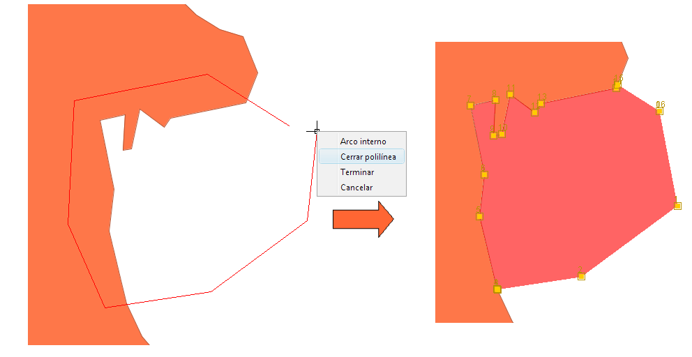
Editing
In this example it is shown how to use a tool already built in another pluggin (extCAD) to inherit from its behaviour and to modify or expand it. In short, it has been implemented a polygon autocompletion feature. The user can draw a polygon and if he/she does it over another existing polygon, the tool takes it into account to follow the boundary between the two plolygons.
The files involved are:
- config.xml.- The extension is defined with the corresponding button and toolbar.
- MyInfoExtension.java.- The class that creates and assigns the tool listener.
- tools/AutoCompletePolygon.java
Graphic Query
This is a typical example of selection by rectangle. It is based on the code of RectangleSelectionListener, and it shows how to work with the selection thru the FBitSet object.
- config.xml.- The extension is defined with the button inside the toolbar workshop.
- SelectExtension.java.- The class that creates and assign the tool listener.
- tools/MySelectRectListener.java
Zoom to selection
Related to the previous example. Once we have a selection, we could analyse it and run any kind of processing over it.
- config.xml.- The extension is defined with the button within the toolbar workshop.
- SelectExtension.java.- Within the class it is discriminated in base of the action-command and the zoom code it is executed.
In the workshop, the ant script that is compiled by the pluggin is build.xml, and in addition to create the .jar, it copies the image directory, the potential libraries owned by the pluggin and the configuration and translation files. It is worthwhile to take a look at it, because it can be used for your own pluggins with little modification (usually variables at the beginning).
Farewell
There are several aspects of gvSIG that we have not seen and they fall outside the framework of this manual. For example, we could talk about at length of these topics:
7.1.- About editing.
7.2.- OGC services
7.3.- Projections
7.4.- Raster
7.5.- Geoprocesses
7.6.- Sextante, 3D, Networks....
These topics are left open and pending for future versions of this manual, with the strong desire that new contributors will join and offer their knowledge in those areas, since I am not the most indicated person to do so in many of the topics.
So this way, let us consider this document as the seed we all can help grow.
The official documentation of the project can be consulted in the developers documentation list, and for anything else, there is always possibility of consulting the developers list
This is it! Happy coding and good luck with the commits ;-)


