


Document Actions
gvSIG-Desktop 1.9. New functionalities
- Labelling
Labelling
Introduction
Layer labels are an independent property of the legend that draws the layer geometry. For this reason, labels have been separated from the legend and are treated as entities in their own right. The entity containing the layer labels is a level (containing text) that is drawn above all the other layers in the legend. Note that labels only make sense in certain environments, e.g. vector layers, annotation.
Labelling can be accessed via the new 'Labelling' tab in the 'Layer properties' dialog box (to activate the 'Layer properties' right-click on the active layer in the Table of Contents (ToC) and select 'Properties' or else double-click on the layer name).
Enable labelling in the Layer properties box
There are two general types of labelling:
1- Static labelling (Using attributes from the layer's attribute table)
2- Advanced labelling (User defined)
To activate labelling the 'Enable labelling' option must be checked.
Static labelling
Static labelling automatically creates labels by using values from an existing field in the layer's attribute table. It has been inherited from gvSIG 1.1 and has almost the same functionality that existed before the implementation of Advanced Labelling in the current version of gvSIG.
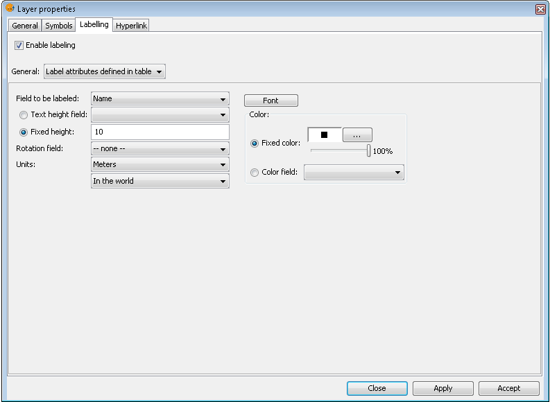
Options for static labelling
These are the options that can be set:
Enable labelling. This enables labelling and displays the layer's labels in the view.
General. For static labelling set this option to 'Label attributes defined in table'.
Field to be labelled. A drop-down list that lets you choose a field in the layer's attribute table that contains values to display as labels.
Text height field option. Select a field in the attribute table that contains the height of each label.
Fixed height option. Enter a fixed value for the size of the labels.
Rotation field. Select a field in the attribute table that denotes the rotation angle of the labels. This must be a numeric field.
Units. Choose the units used for the height values.
Font. Select the font to apply to the labels.
Fixed colour option. Choose a colour for the labels. You can also set the label transparency by using the slider.
Colour field option. Select a field in the attribute table that contains colours.
Advanced Labelling (user defined)
Introduction
User defined labelling provides the user with a great degree of control over the design and placement of labels. It has many more options and is much more powerful than static labelling.
The three different methods of user defined labelling are described below.
Label features in the same way
Choose this option to apply the same label style to all features in the layer, regardless of whether they have been selected or not.
The interface for this labelling option looks like this:
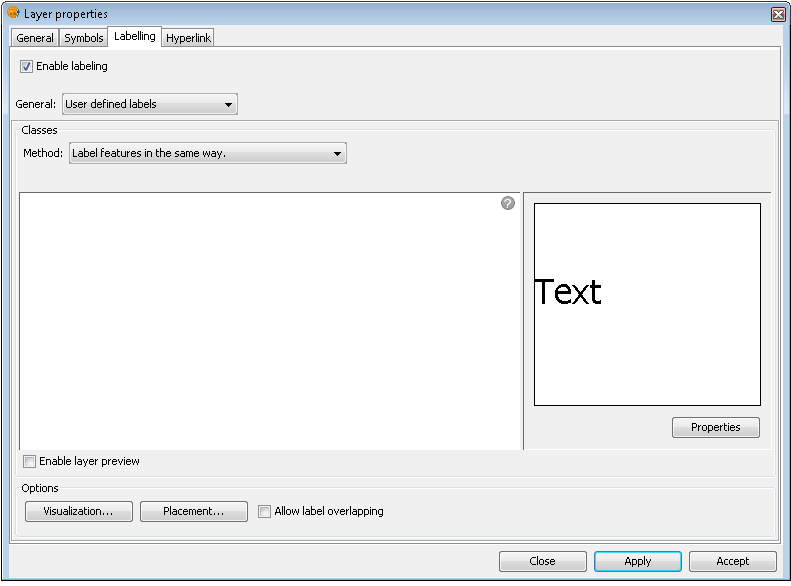
Label all features in the same way
Note the following options, which are explained below:
- Properties
- Visualization
- Placement
It is also possible to preview the labels that have been defined for the layer. These will be applied to the View if the Apply or Accept buttons are clicked.
Label only when the feature is selected
Apply the label setting only to those features that are selected in the View.
This labelling is dynamic, so that if the selection in the View is changed, the View is automatically updated with the labels for the new selection.
The interface for this labelling option is the same as that shown above (Label features in the same way).
Define classes of features and label each differently
With this option the user can create different label classes (through the 'Add' button), assign them a priority for display (using the 'Move up' / 'Move down' buttons to the right of the panel) and label each one separately.
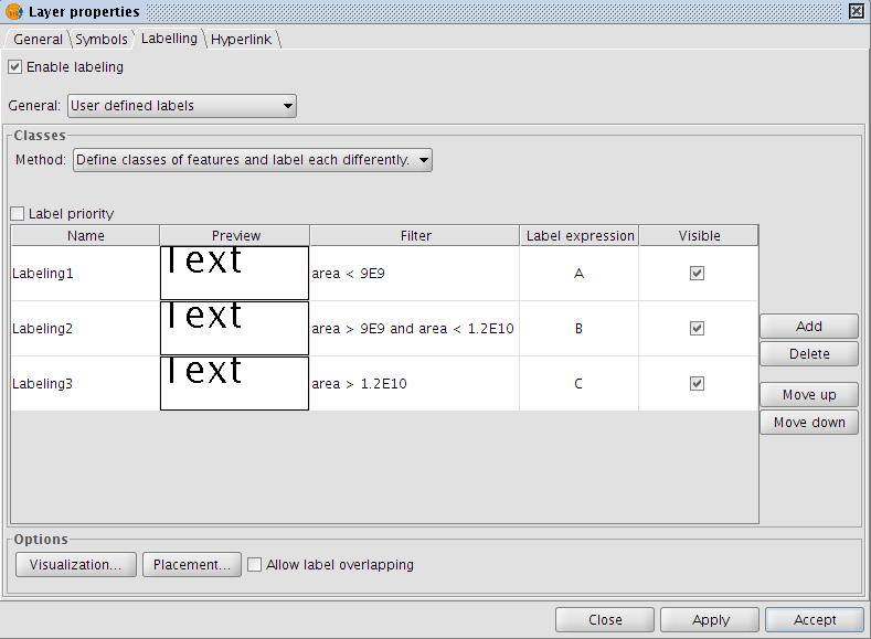
Advanced labelling. Different classes and labelling
The properties for each class can be accessed by double clicking on the relevant class (This brings up a dialog box, which is the same as for the three existing advanced labelling methods).
In other words, the label classes can be configured separately, with different labelling properties and different filters applied to the layer geometry for each class. Keep in mind that the labelling expression uses SLD grammar, while the geometry filter is applied using SQL statements, as defined by GDBMS.
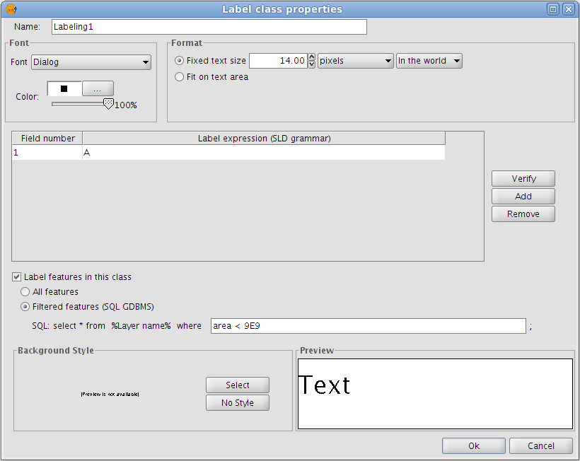
Advanced labelling. Property Configuration
The dialog box below shows how SQL statements can be entered for each of the label classes. These statements act as filters that determine which of the layer's features the class is applied to.
Here is an example of how this SQL filter is used:
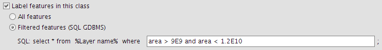
SQL statement for filtering features
Common options
Introduction
Regardless of which advanced labelling method is chosen, there are some options that are common to all three methods. These options provide a great degree of control over the configuration of the labels.
These options are accessible via the buttons on the labelling tab of the Layer properties dialog box and are described below.
Properties
The 'Properties' button provides access to a large number of label options.
Clicking this button opens the dialog box shown in the figure below:
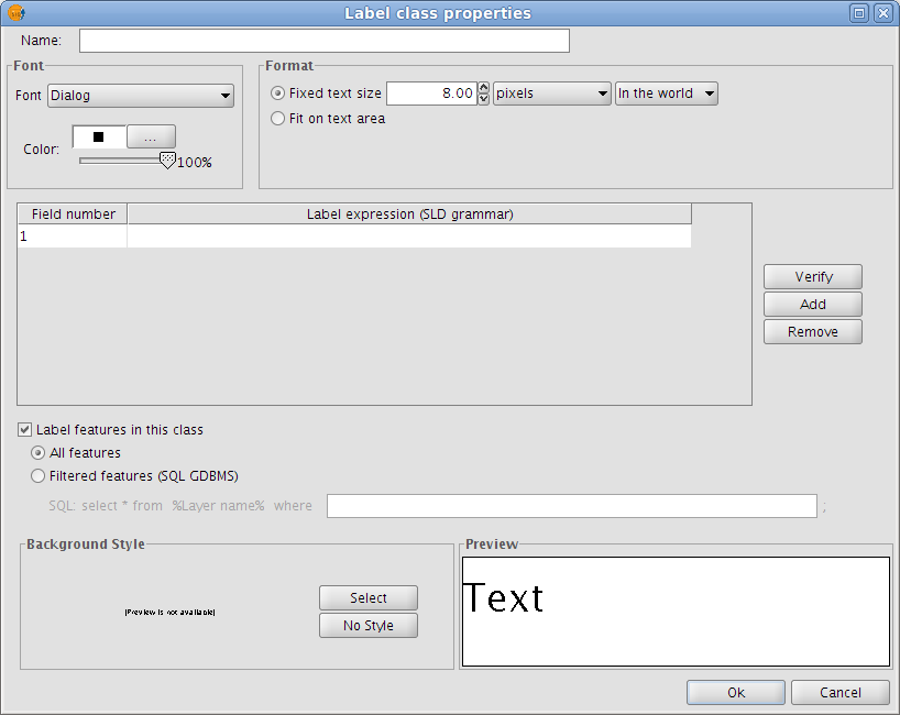
Label class properties
The following properties can be set in this dialog box:
Name
Font type
Font colour
Text size (fixed size or adjusted to fit on text area)
Label expression (one or more)
This is where the actual label is specified. The possibilities are:
- Strings (enclosed in quotes)
- Fields from the attribute table (enclosed in square brackets)
- Mathematical expressions
- Combinations of the above
Label all features / filter features with a SQL statement
The SQL filter allows the user to apply the defined label to certain features only.
Background style
Select a style (picture) as a background for the labels. Clicking the 'Select' button opens the following dialog box:
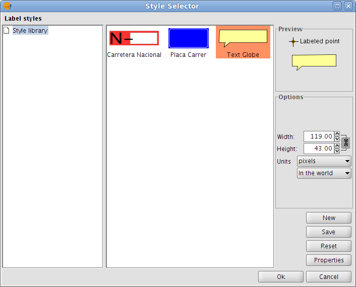
Select a label background style
When gvSIG is installed, the installer automatically creates a directory called 'Styles' in the directory /user/gvSIG/. This is where all the label styles are saved (by clicking the 'Save' button).
Once a label style has been selected, it is possible to modify its properties by clicking the 'Properties' button. This opens a dialog box (shown below) where the user can insert one or more text boxes in which to place the different label expressions that have been created. These text boxes can also be moved or deleted and it is also possible to upload a new image from disk.
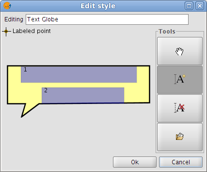
Configure the label background style
Note: It is not possible to apply a background style if the label orientation is set to "Following the line" (see the Placement section below).
Placement
Clicking the Placement button opens the Placement properties dialog box where the following properties can be configured: location, orientation, duplicates, etc. The options available in this dialog box will depend on the geometry of the layer in question (point, line or polygon):
Point layer
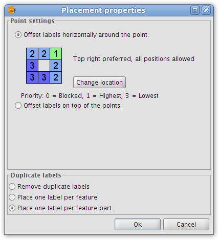
Placement properties for a point layer
If the layer is a point layer, the following options can be configured:
- Point settings
This options allows the user to place the labels on top of the points, or else to offset them around the points.
In the latter case, the label position can be selected from pre-defined placement configurations, which are accessed by clicking the Change location button. This opens the Placement priorities selector from where existing placement styles can be selected. It is also possible to modify a placement style by highlighting it and clicking the Properties button:
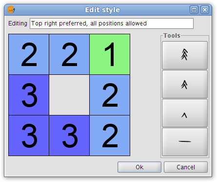
Label priority placement around a point feature
By using the tools on the right and applying them to the location grid on the left it is possible to set the label position priority relative to the point:
1 = High precedence
2 = Normal precedence
3 = Low precedence
0 = Prohibited
- Duplicate labels
Here it is possible to choose between 'Remove duplicate labels' (eliminate any duplicate labels and only draw one label per feature), 'Place one label per feature', and 'Place one label per feature part' (in the case of multipoint features).
Line layer
For line layers the following options are available:
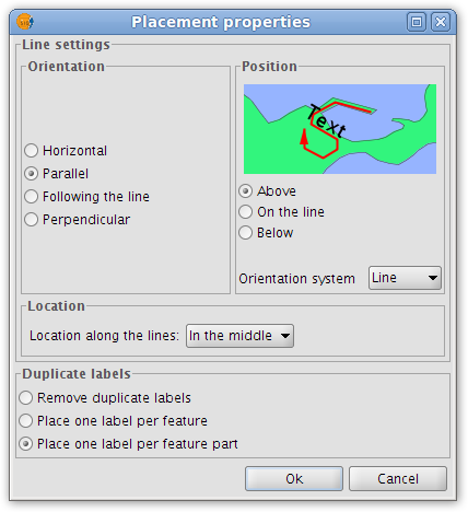
Placement properties for a line layer
- Orientation
The label can be oriented horizontally, parallel or perpendicular to the line, or can be set to follow the line.
- Position
The label can be placed above, on or below the line.
- Location
Place the label at the beginning, middle or end of the line, or at the best position.
- Duplicate labels
The options here are the same as for point layers (described above).
Polygon layer
If the layer is a polygon layer, the Placement properties dialog box provides the following options:
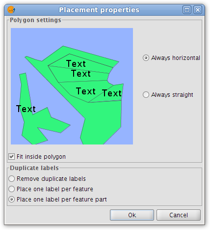
Placement properties for a polygon layer
- Polygon settings
Labels can be set to be always horizontal, or else to follow the orientation of the polygons (always straight). There is also an option for fitting the labels inside the polygons. This last option is used to ensure that labels are placed inside polygons even if they have islands, or are U-shaped.
- Duplicate labels
These options are the same as for point and line layers.
Multigeometry layers
In the case of multigeometry layers (dwg, dxf, gml...) the Placement properties dialog box contains a tab for each of the three geometries (points, lines, polygons). These tabs are identical to those shown above.
Visualisation
Clicking the 'Visualisation' button opens a dialog box which allows configuration of the range of scales at which labels will be shown.
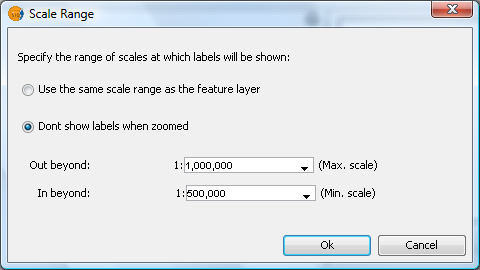
Scale range for a layer's labels
The user can choose to use the same scale range as the feature layer (set under the General tab of the layer properties dialog), or else can specify a scale range at which the labels will be visible (this scale range is independent of the range applied to the geometries of the layer).
In the example shown above, labels in the view are only displayed between the scales of 1:500000 and 1:1000000.
Allow label overlapping
Finally, there is a check box that controls whether labels may overlap or not.
If this box is checked then all labels are drawn, even if they overlap each other. If this box is left unchecked, only non-overlapping labels are drawn and all overlapping labels are eliminated.
Single labelling
In addition to static labelling and user defined advanced labelling, there is a third type of labelling, namely Single Labelling, which can be accessed via the following icon on the toolbar:

Single labelling icon
This type of labelling supplements the existing functionality of annotation layers. In fact, single labelling allows the user to create personalised annotations that have not been possible till now.
The result is an annotation layer, of type shape, plus a file with a .gva extension.
This type of labelling acts only on the geometry that the user has selected in the gvSIG View.
As with advanced labelling, valid label expressions can take on a number of forms:
- Strings
- Fields from the attribute table
- Mathematical expressions
- Combinations of the above
The advantage of Single Labelling over static or user defined labelling, aside from the availability of the many annotation layer labelling options, is that individual labels can be modified and/or moved after they have been created. This is because the labels are in a new, independent layer that can edited just like any other vector layer.
The steps for using this type of labelling are described below:
Configure the annotation properties:
From the main window of this tool, the user can set some basic properties that will apply to the new annotation labels (default annotation properties can be defined in the Annotation properties section of the gvSIG Preferences).
- Font type
- Font style
- Font height
- Font Colour
- Font Rotation
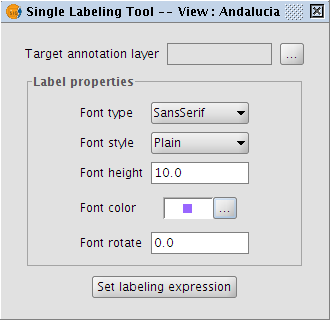
Properties of the annotation being created
Configure the target annotation layer:
As shown in the following dialog box, it is possible to open an existing annotation layer from the hard drive, create a new one in the specified location, or to select one that has already been loaded into the View:
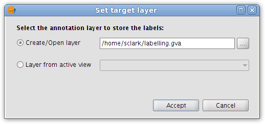
Destination of the annotation layer
Define a labelling expression:
Activate the source layer in the ToC, click the Set labelling expression button and then define an expression in the text box next to the layer name.
An example of this step is shown below:
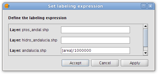
Annotation labelling expression
In the View click on the features that need to be labelled.
In this way, labels are inserted into the View as each of the features is clicked. The labels are drawn according to the label properties set above.
Finally, opening the Layer properties for the annotation layer reveals that a new 'Annotation' tab has been added to the dialog box.
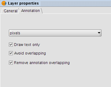
Annotation tab in the Layer properties dialog box
In this tab it is possible to configure a number of annotation options:
- Measurement units (any of the measurement units supported by gvSIG may be selected)
- Draw text only
- Avoid overlapping
- Remove overlapping annotation


